

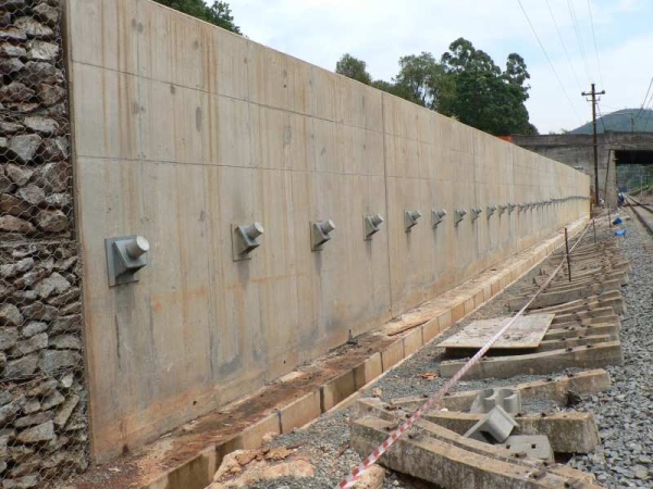
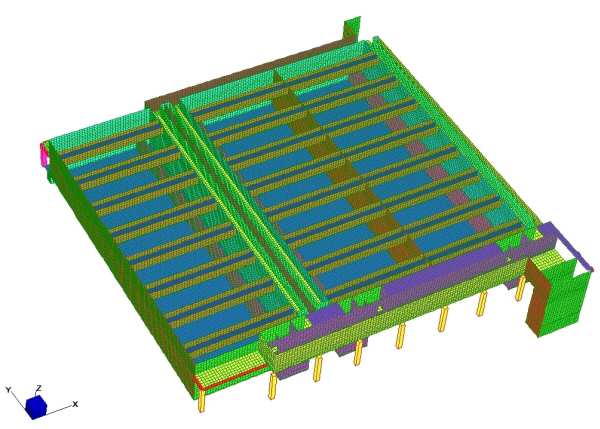
This cylindrical post-tensioned reservoir, designed during 2015, is currently under construction. This is probably one of the largest cylindrical post-tensioned concrete reservoirs in the world, with an inner diameter of 154 m and a wall height of 11,8 m. The reservoir is covered by a flat slab roof supported by 272 columns spaced at 8,4 m. Since the reservoir is 6 m below natural ground level, both a leakage detection system and a ground water drainage system, separated by a reinforced flexible polypropylene liner, is provided underneath the complete footprint of the reservoir.
Particular attention is given to the concrete mix designs, such as the following:
The reservoir contains approximately 16 300 m3 of concrete, 8 000 m3 of no-fines concrete and 2 250 ton of (non-prestressed) reinforcement.
The humidity above all slab panels was increased with handheld high pressure mist sprayers during casting from the time that concreting commenced until completion of final finishing to prevent plastic shrinkage cracking. After final finishing, slabs were protected with plastic sheets, until water curing started the following day. Temporary brick walls were built on the perimeter of each individual pour to allow flooding of the particular floor panel.
Construction of the reservoir has been successful completed.
(updated 10 January 2024)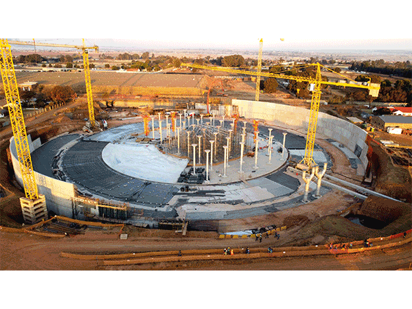
(As specialist sub-consultant to Bosch Projects (Pty) Ltd)
Structural analysis and design of embankment type reinforced concrete tanks for the storage of crude oil. The first phase of the facility consists of an array of nine tanks, each with a capacity of 175 Mℓ. Currently seven of these are in operation, with no signs of oil leakage. The tanks are square with splayed corners in plan, with a propped cantilever wall on the perimeter founded on an embankment. The internal tank size between walls is 110 m, and the maximum fluid depth is 17 m. The wall is approximately 9,3 m high, 800 mm wide at the bottom and 400 mm wide at the top. The tanks are covered with flat slab roofs with drop panels, and are backfilled to the top of roof slab level. An eighth of a tank together with the embankment was modelled with Strand7 finite element analysis software. Three conditions were investigated, i.e. tank filled with fluid and no backfill, backfilled tank with no fluid, and backfilled tank with fluid. The tanks have been designed as jointless with construction joints only.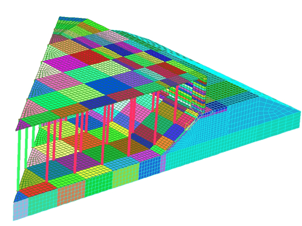
(As specialist sub-consultant to BSM Baker (Pty) Ltd)
Structural design of a cylindrical reservoir with a flat slab roof and a post-tensioned wall. Except for the sliding joint between the wall and floor slab sealed with a bandage system, and the sliding joint between the roof slab and the wall, the reservoir has been designed as jointless.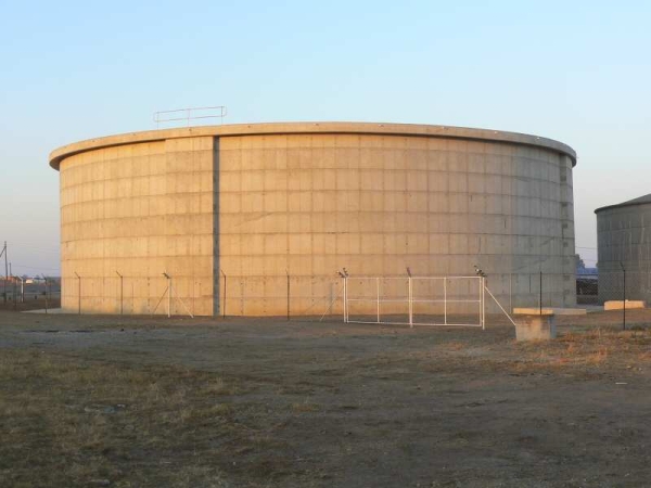 .
.
Structural design of a cylindrical reservoir with a flat slab roof and a post-tensioned wall. Except for the sliding joint at the bottom of the wall sealed with a bandage system, and the sliding joint between the roof slab and the wall, the reservoir has been designed as jointless.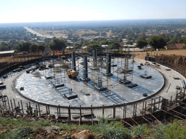 .
.
The project comprised a 3 Mℓ and 5 Mℓ reinforced concrete process water tank, both of which have been found on piles due to poor founding conditions.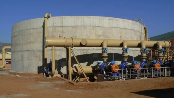 .
.
The project comprised a 9,5 Mℓ post-tensioned reservoir, 12 Mℓ reinforced concrete process water tank and 8 Mℓ post-tensioned dirty water tank.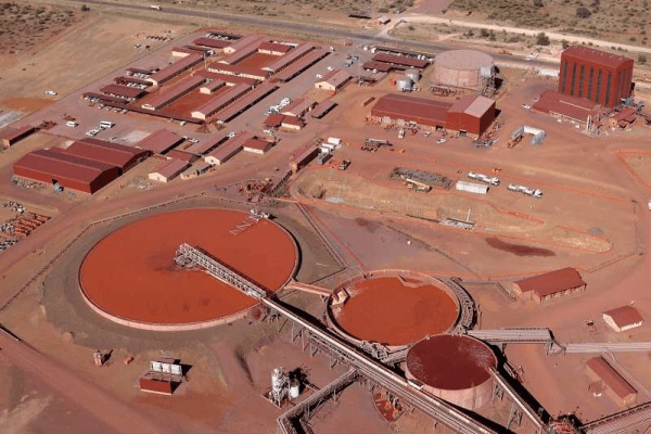 .
.
Cracks up to 20 mm wide developed in the gravity type mass concrete wall of this reservoir which was constructed in 1953. Despite various attempts to repair the reservoir, it had to be de-commissioned in 2001 due to excessive leakage and concerns regarding structural safety. The reservoir was rehabilitated by constructing a post-tensioned concrete wall on the inside of the existing wall, and lining the reservoir with a 2 mm ethylene vinyl acetate liner.
(As specialist sub-consultant to Nyeleti Consulting (Pty) Ltd)
This post-tensioned reservoir, which is underlain by dolomite, experienced up to 200 mm settlement over ± 25% of its floor area (including wall footing). Settlement was solved with ground improvement by compaction grouting by others. Structural work comprised repair of the settled wall footing and floor slab, lining the reservoir with a 2 mm thick ethylene vinyl acetate (EVA) liner and installation of a leakage detection and drainage system underlain by another EVA liner to prevent leakage water from penetrating into the soil.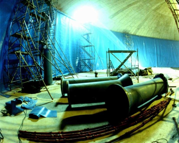
(While being employed by BKS (Pty) Ltd)
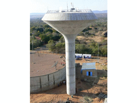
The structure is 32 m high, and consists of a reinforced cylindrical shaft and conical bowl.
(While being employed by BKS (Pty) Ltd)
The main structural elements of this 46 m high tower are a conical outer shell, a cylindrical shaft, a floor slab with precast concrete beams and in situ slab midheight supporting the water and a roof slab with precast prestressed concrete I-beams and precast concrete panels, covered with a structural screed. The water-retaining part of the conical shell is post-tensioned.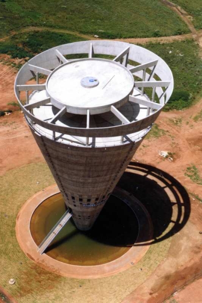
(While being employed by BKS (Pty) Ltd)
Structural work included reinforced concrete inlet works, chlorine contact tank, screw pump station, clarifiers and 50 m diameter reactor.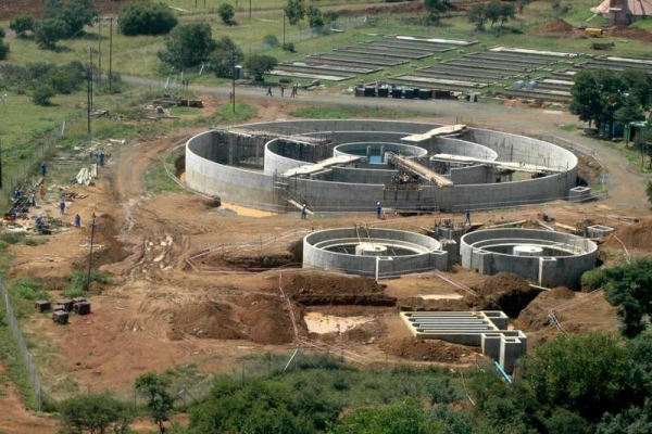
(While being employed by BKS (Pty) Ltd)
Part of the four man structural design team, and responsible for the design of Level 2 to 5 slabs, ramps, Western Access and brickwork details, and calculation of expected movements at expansion joints.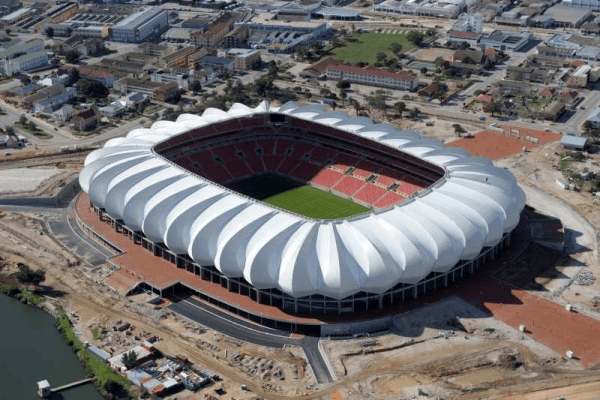
(As sub-consultant to Kwezi V3 Engineers and Ndodana Consulting Engineers (Pty) Ltd)
The pavilion is a five storey reinforced concrete structure with a cantilever structural steel roof. Besides structural design of the complete pavilion, a sun study was performed to determine geometry of sun shades for spectators and sight lines were checked.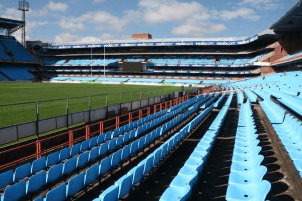
(While being employed by BKS (Pty) Ltd)
The building comprises a structural steel frame (± 400 ton steel) with precast floor slabs. The programme was extremely tight, with final structural design starting at the end of April 2008, construction starting at the beginning of June 2008, and partial occupation of the building for registration of students in December 2008. Despite the time constraints, a strict quality assurance regime was followed. As a result all structural steel members were inspected and stamped, and all welds were tested prior to installation. Responsibilities also included stability of brickwork and provision of brickwork details.
Structural design of the three storey reinforced concrete office building and structural steel roof.
(As sub-consultant to Daling, De Lange & Van Tonder (Pty) Ltd)
The project comprised the modification of the existing 51 m high steel structure to support newly designed air heating equipment and ducts. The structural analysis was preformed by others, and responsibilities included evaluation of existing members under modified loading, and design of new steel members and connection details.
(As sub-consultant to BKS (Pty) Ltd)
The plant, consisting of a Radiant Section, Convection Section, Auxiliary Boiler and Stack, is situated in earthquake Zone 4. The seismic analysis was performed by others and responsibilities included the design of structural steel elements and connections in accordance with the American Institute of Steel Construction’s Allowable Stress Design Code.
(While being employed by BKS (Pty) Ltd)
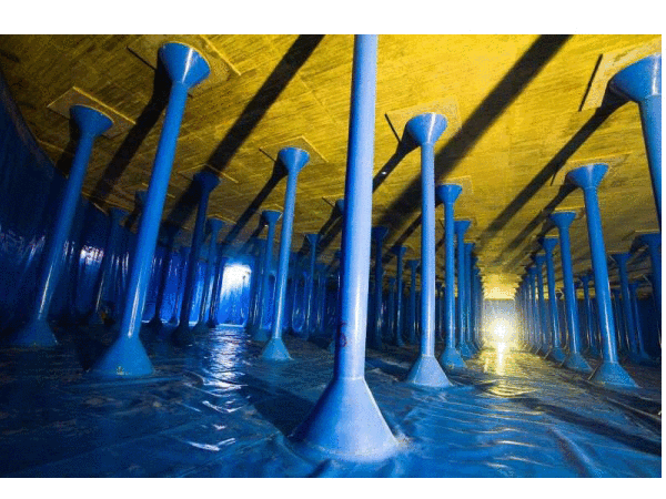
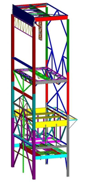
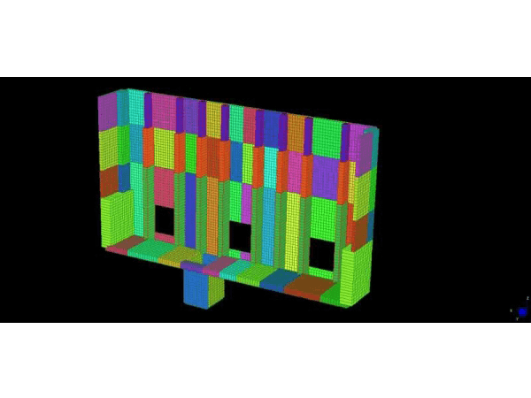
This reinforced concrete silo is 38,75 m tall, with an inner diameter of 21 m and a wall thickness of 385 mm. On level 14,500 there is a 1,5 m deep floor slab with radial beams and a circumferential beam. Large openings for conveyors are created at the bottom of the silo wall. The wall and floor slab is supported by 5 columns, approximately 2 m x 2 m. In May 2018, after completion of sliding of the wall, it was discovered that the wall was oval and skew, with maximum plan section deviations of +350 mm (outwards) and -350 mm (inwards). The as built silo was scanned, and the distorted silo geometry was imported in Strand7 to investigate the effect of the distortion on forces and moments with a finite element analysis. The design verification showed that the capacity of horizontal reinforcement in the wall between levels 15,500 and 30,500 was between 75% and 95% of the required capacity, and that two columns underneath the wall had insufficient capacity. The following options were investigated:
The last option was the most beneficial and was modelled in Strand7 (on the image of the model a quarter of the silo is cut away to show the inside). Two columns are strengthened outwards, and the wall is strengthened with 10 fins at 2 m centres from level 14,500. The contact surface of the wall at fins was roughened, and the fins are connected to the wall with Y12 dowels. Approximately 6000 dowels were installed, and were subjected to a strict pull-out testing regime. Strict water curing was done on the fins.
(As specialist sub-consultant to bvi Consulting Engineers Gauteng (Pty) Ltd)
The work comprised the structural design of various structures such as culvert flow transitions, energy dissipating structures and valve chambers. Approximately twenty-five types of valve chambers were designed for pipes up to 1 600 mm diameter, and forces up to 5 650 kN acting on the chamber walls. The biggest chamber had internal dimensions of 10,5 x 9,5 x 5 m high, and a wall thickness of 1 m. All structures had to be designed as water-retaining.
(As specialist sub-consultant to Ndodana Consulting Engineers (Pty) Ltd)
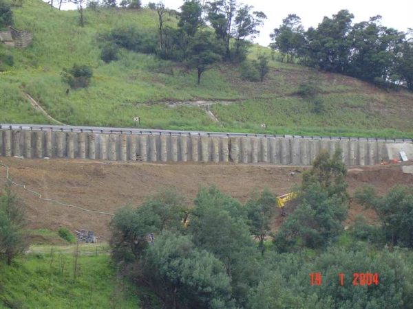
A landslip adjacent to the main Durban-Johannesburg electrified railway line threatened operation of the rail line and safety of a housing development close to the railway line. The concept by a geotechnical engineer comprised the installation of 39-750 mm φ piles at 2000 mm spacings, socketed into rock, with a 75 m long reinforced concrete retaining wall connected to the top of the piles and restrained horizontally with soil anchors at 2000 mm spacings. Due to the presence of stray currents, cathodic protection had to be used to prevent corrosion of reinforcement.
For more than a decade this embankment had experienced persistent displacement. The concept by a geotechnical engineer comprised the installation of 51-1000 mm φ piles at 2000 mm spacings, socketed into rock, and supported by ground anchors at the top, and with pneumatic concrete between piles. Due to the acidic nature of the soil with a pH as low as 4,8, a blend of CEM I 42,5 (ordinary portland cement), ordinary fly ash and ultra-fine fly ash was used as cementitious material, and 3CR12 reinforcement.
(While being employed by BKS (Pty) Ltd)
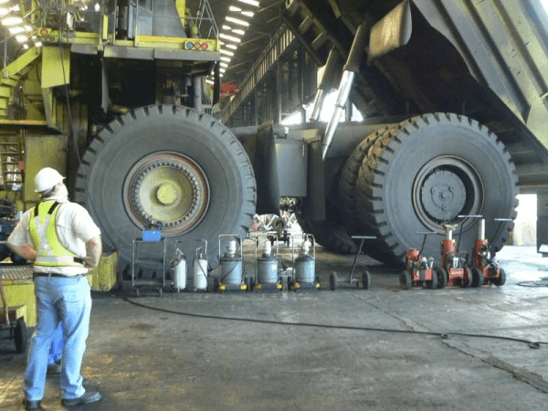
The concrete surface bed of the Workshop, which is used to service heavy mining vehicles with a mass of up to 435 t, displayed defects such as severe cracking, concrete spalling at joints and penetration of wash water into the layerworks. A failure investigation was conducted in collaboration with a geotechnical and pavement engineer to determine the cause of the problems. Four adjacent panels of the surface bed were modelled with Strand7 finite element analysis software with boundary conditions to simulate the interaction at joints between panels. The layerworks underneath the surface bed was modelled with properties obtained from laboratory test on the different layers in a test put which was dug in the workshop. Two types of loading were investigated. i.e. vehicle loads and loads of jacks, and a non-linear analysis was performed. The analyses indicated that for vehicle loads, the flexural tensile strength of the surface bed is exceeded, and that under jack loads both the flexural tensile strength and allowable punching shear stress are exceeded. The investigation concluded that the surface bed had reached the end of its service life and needs to be replaced.
These rectangular reservoirs with capacities between 7,5 and 9 Mℓ, and constructed between 1976 and 1979, had over the years developed signs of serious structural distress, including various combinations of the following: relative displacement of the top of wall panels, widening of certain joints, tearing of hypalon bandages at floor to wall footing joints, leaks through wall joints, local spalling at joints, and a level difference between floor slab and wall footing. Failure finite-element analyses and hand calculations indicated that the allowable bearing capacity of the soil had been exceeded leading to large failure zones in the soil and causing rotation of wall panels, and that sliding of wall panels had occurred. The outcome of the investigation was that due to a high risk of failure, rehabilitation of the reservoirs was not viable.
Finite element analyses and design of the following were done: 18 Mℓ jointless rectangular reservoir, filters, clarifier and chemical building.
(While being employed by BKS (Pty) Ltd and as sub-consultant to BKS (Pty) Ltd)
The work comprised the structural design review of the upstream and downstream walls of the Turbine Chamber, the Draft Tube wall and the canal walls of the Forebay. Most of the Turbine Chamber is below ground level, with walls approximately 17 m high. The walls are stiffened by large columns. The walls were analysed with finite elements in Strand7 software. The Draft Tube wall is a retaining wall cantilevering approximately 11,5 m. The Forebay canal walls also act as cantilevers to retain water to a maximum depth of approximately 9 m.
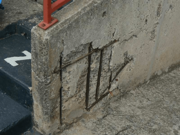
A visual structural audit revealed serious concrete deterioration at localised positions in the stadium. The areas were measured to determine quantities and indicated on rehabilitation drawings. Specifications for the different types of concrete rehabilitation required were compiled, and the project was put out to tender. The work was completed successfully and has increased the design life of the stadium.